Define the panel
Dimensions, density, surfaces, core structure, reinforcement, joints and intended wall use.
Panel structure, moulds, reinforcement or facing, curing, cutting, slotting, demoulding and handling must work as one production route.
Dimensions, density, surfaces, core structure, reinforcement, joints and intended wall use.
Select the applicable mould direction, pouring sequence and curing positions.
Coordinate cutting, slotting, demoulding, transfer and stacking.
Match mould quantity, curing time, labour, factory space and expected output.
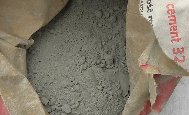
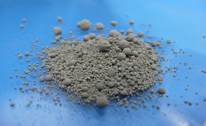
ENGINEERING DRAWING Prepare repeatable slurry batches for the confirmed panel material system.
Read more →
ENGINEERING DRAWING Connect pouring, curing, demoulding and return movement.
Read more →
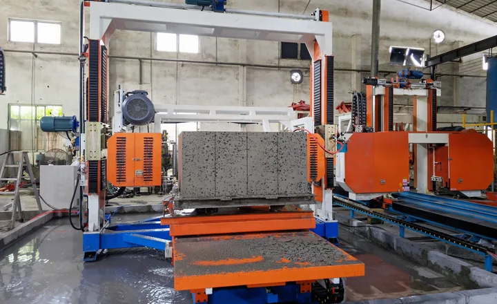
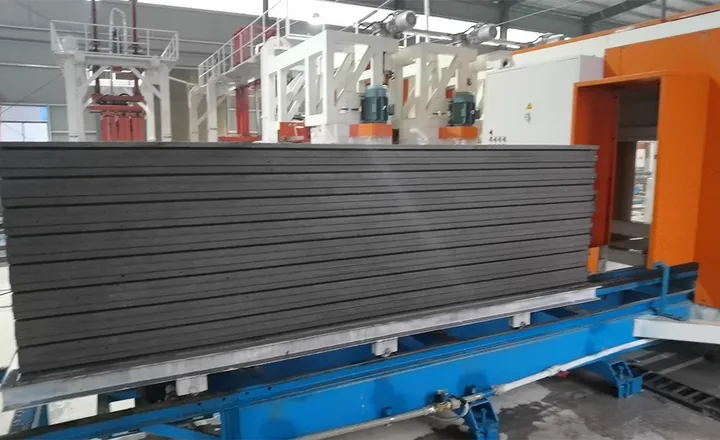
REAL FACTORY EQUIPMENT Match the panel dimensions, surfaces and joint or groove requirements.
Read more →
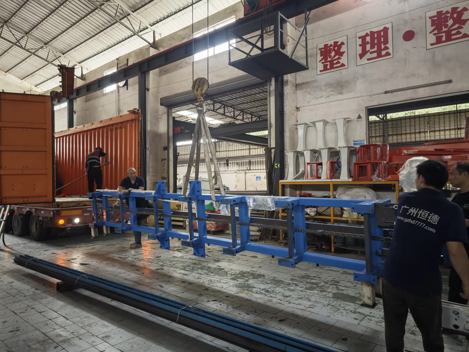
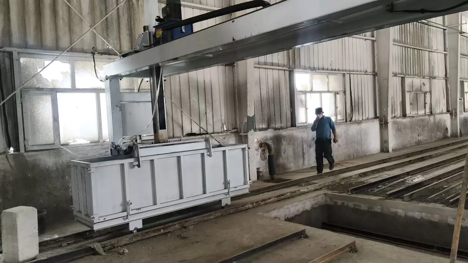
REAL FACTORY EQUIPMENT Protect the panel while moving it through demoulding, finishing and storage.
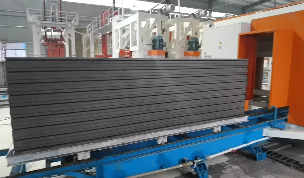
Read more →The machine, product condition and required groove profile must be reviewed together. This original close-up documents a real grooved lightweight product; the final profile follows the confirmed product drawing.
Reference directions around 80, 150 and 200 m³/day help frame the discussion, but the finished panel and complete factory rhythm determine the final scope.
Frame a compact wall-panel route around the confirmed product, mould cycle, curing time, cutting and handling rhythm.
Connect additional mould circulation, cutting and handling capacity around the approved factory plan.
Review a project-specific route connecting premixing, powered storage, nine-station horizontal cutting, CNC vertical cutting, slotting, mould circulation and centralized control.
Read more →
Tell us the project country, target product, local raw materials, planned output and current project stage.

Engineering can only configure a practical line when the real production conditions are visible.