
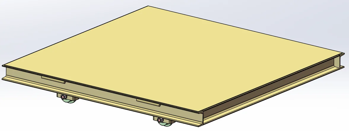
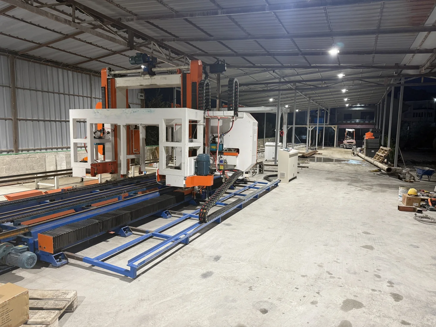
 Tirana, Albania
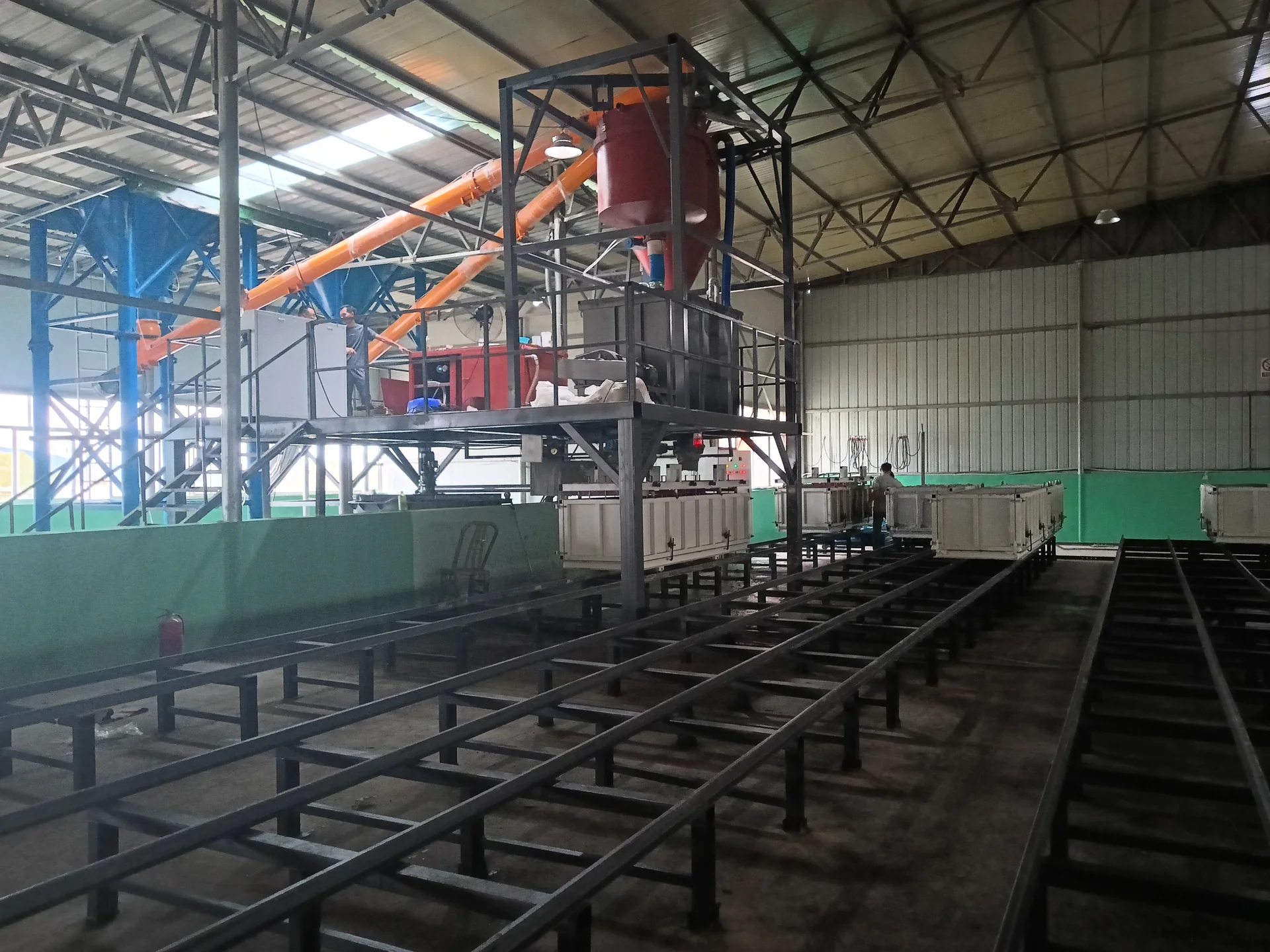
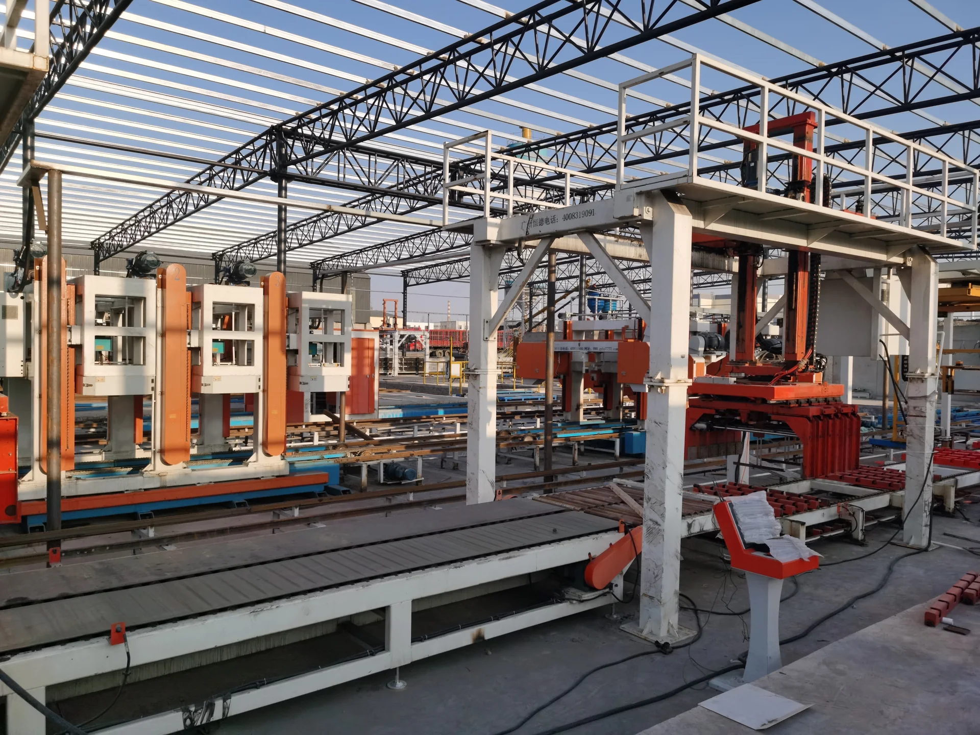
 Albania 100 m³/day foam-concrete block production line
- Product
- Foam-concrete blocks
- Capacity
- 100 m³/day project basis
- Project Stage
- Line operating at site
CLC PHYSICAL-FOAMING LINE
PROCESS ROUTEPhysical foaming · Non-autoclaved curing
CLC / foam concrete block production using physical foaming and non-autoclaved curing. Explore the line visual, production stages, equipment configuration, project examples and installation support.
Get a Production Line Proposal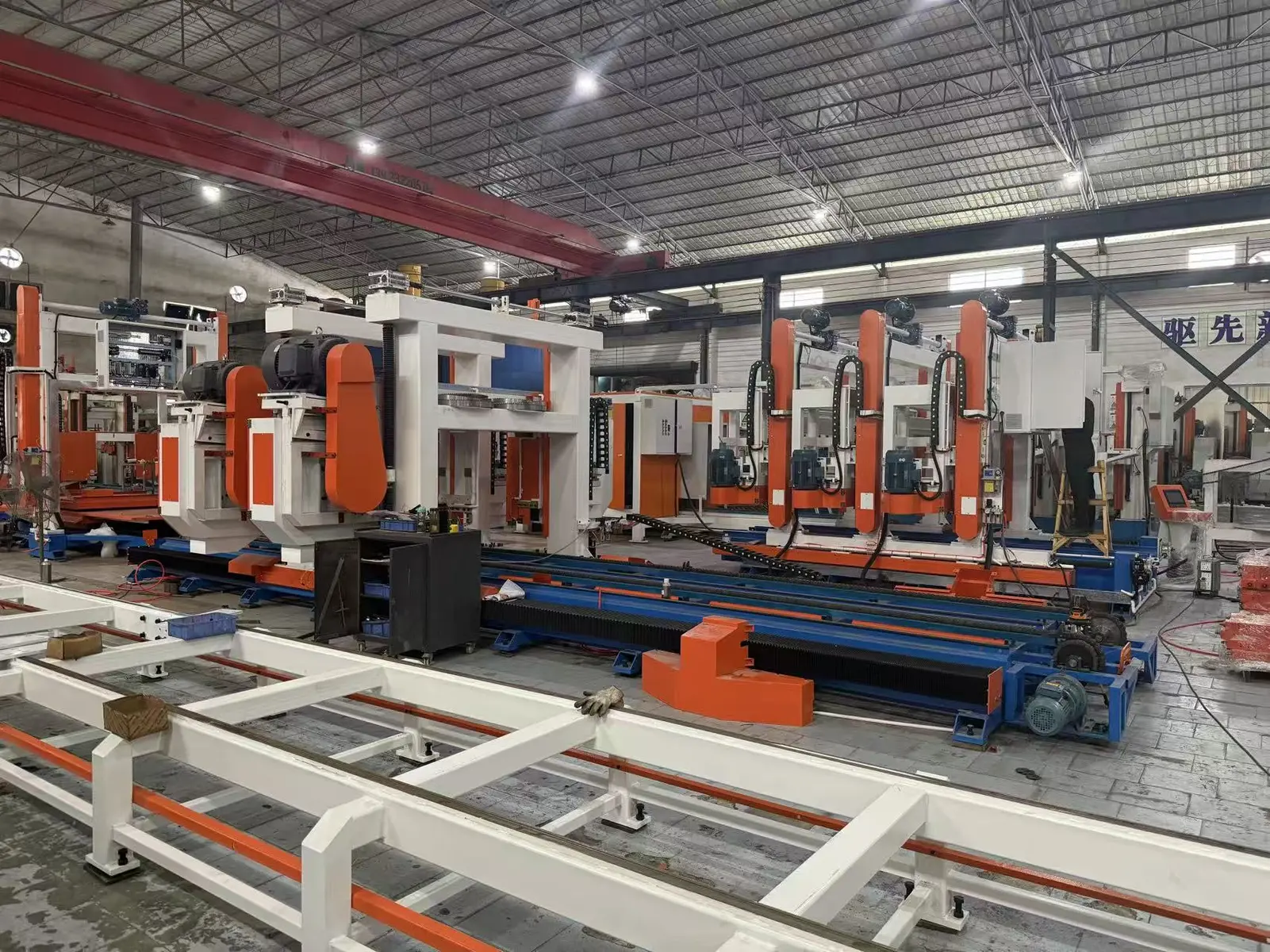 Open full-size image
CAPACITY QUICK INFORMATION
SOURCE-BACKED CAPACITY DIFFERENCES
SIX-STEP PROCESS
Feed and weigh the confirmed powder, aggregate and water inputs.
Prepare preformed physical foam with the source-listed foaming machine and combine it with the metered slurry.
Fill the mould configuration selected for the block product and production capacity.
Match the non-autoclaved curing time, mould count and demoulding condition to the product.
Use only the cutting architecture listed for this capacity and variant.
Move finished blocks through the source-listed handling and stacking scope.
COMPLETE EQUIPMENT CONFIGURATION
Review the equipment for each production stage. Select an equipment image to enlarge it, or open a linked equipment name for more detail.
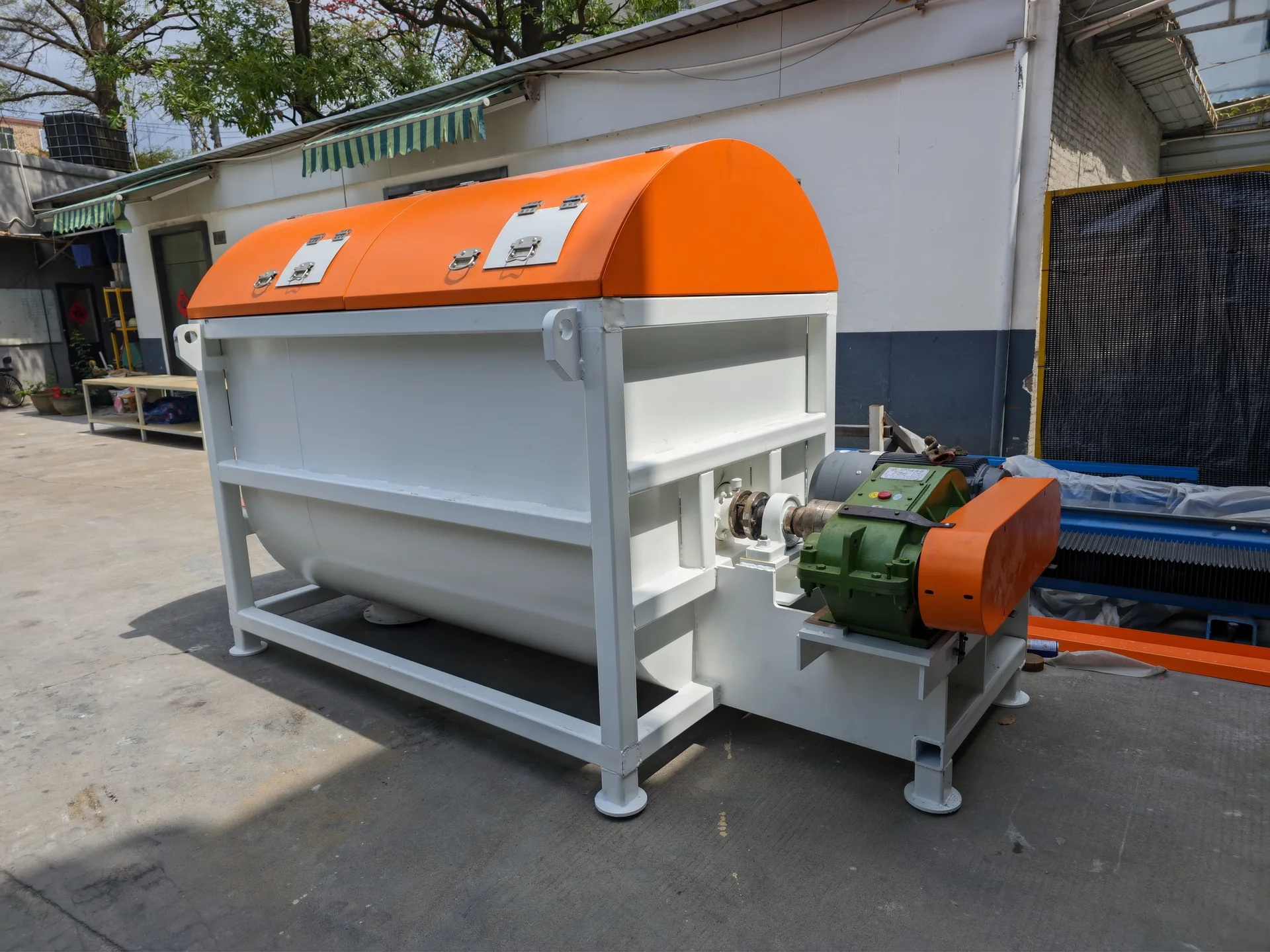
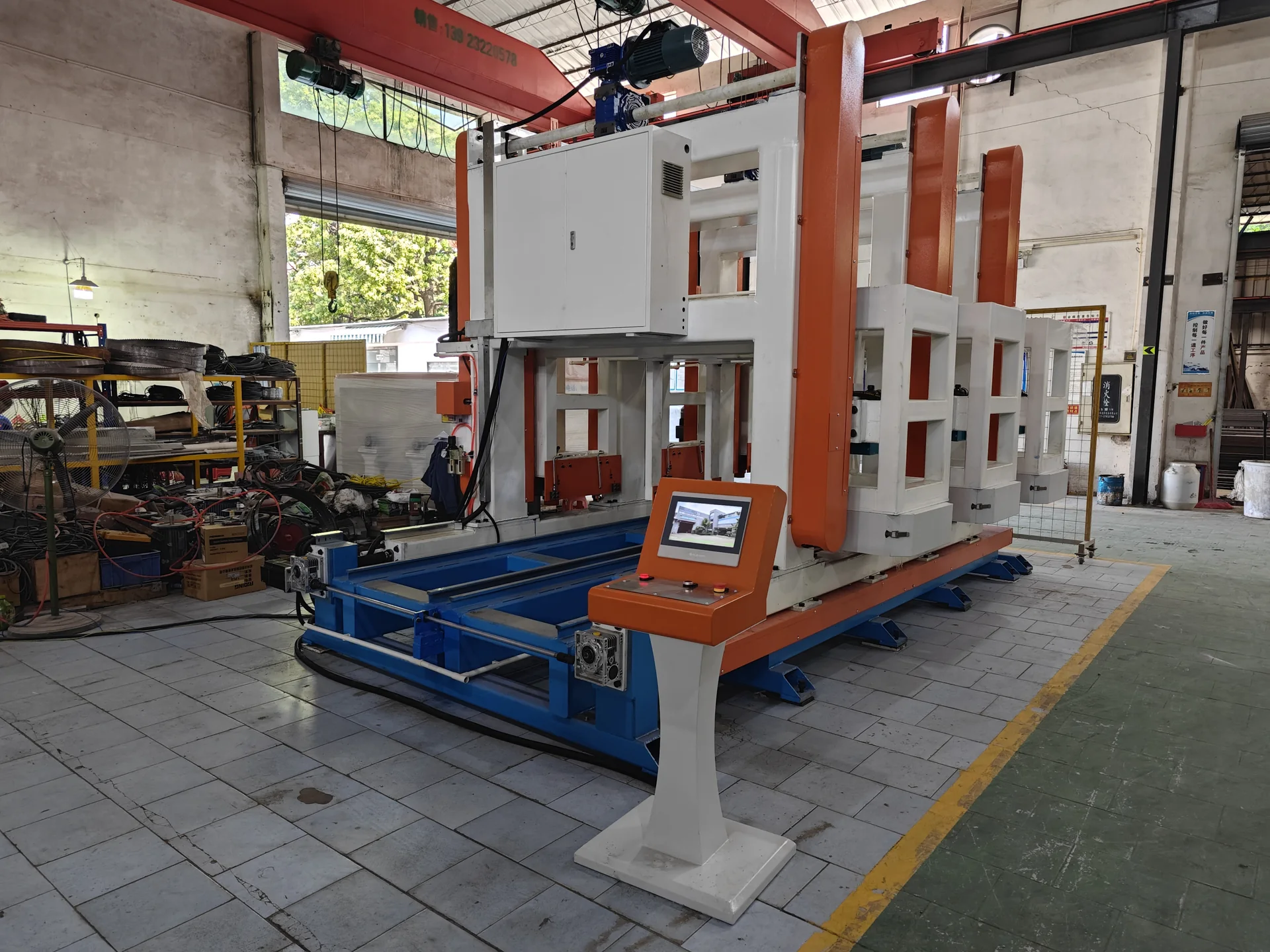
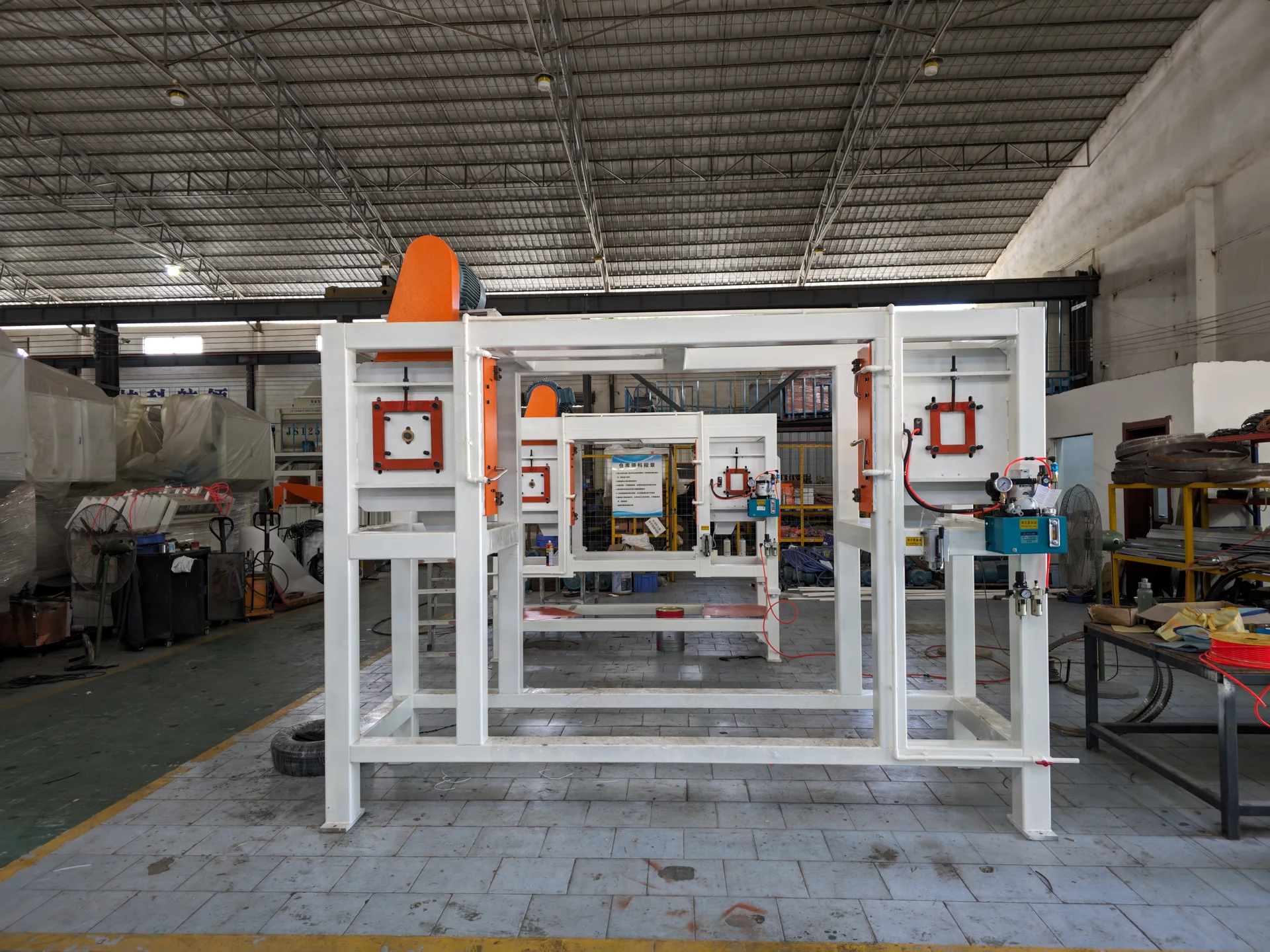
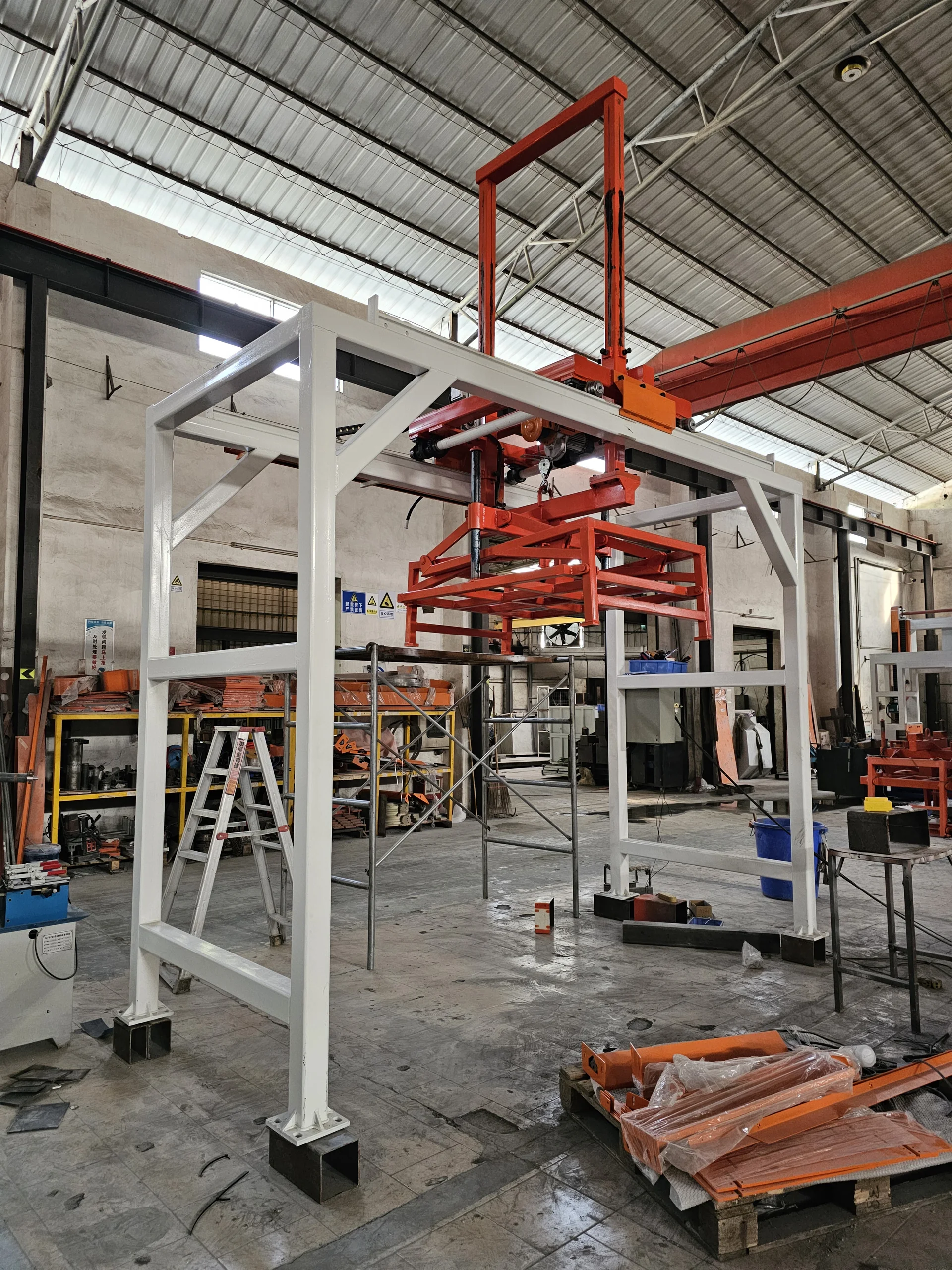
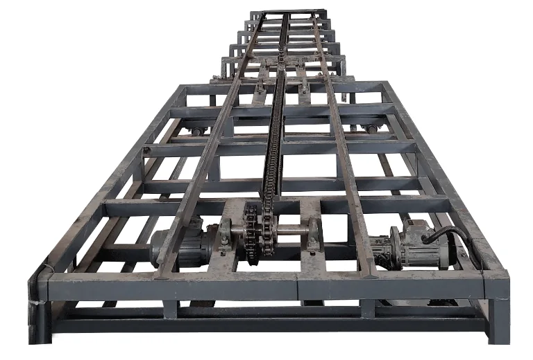
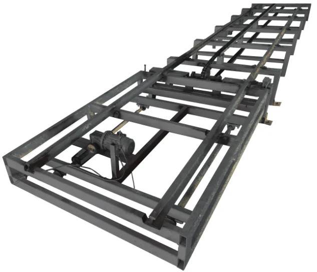
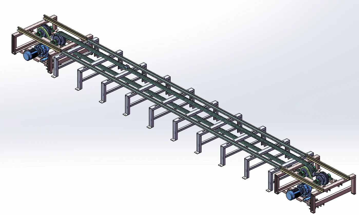
| No. | Equipment | Stage | Model | Dimensions | Qty. | Unit power | Total power (kW) |
|---|---|---|---|---|---|---|---|
| Preparation & metering | |||||||
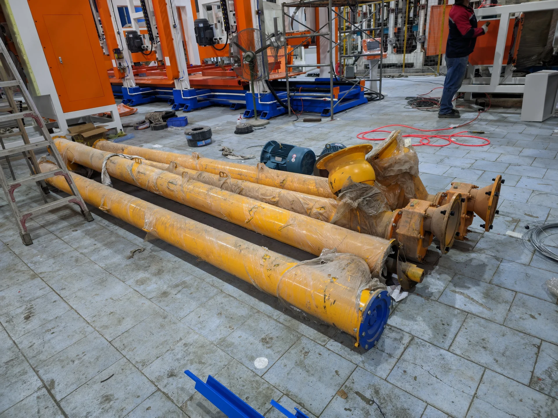
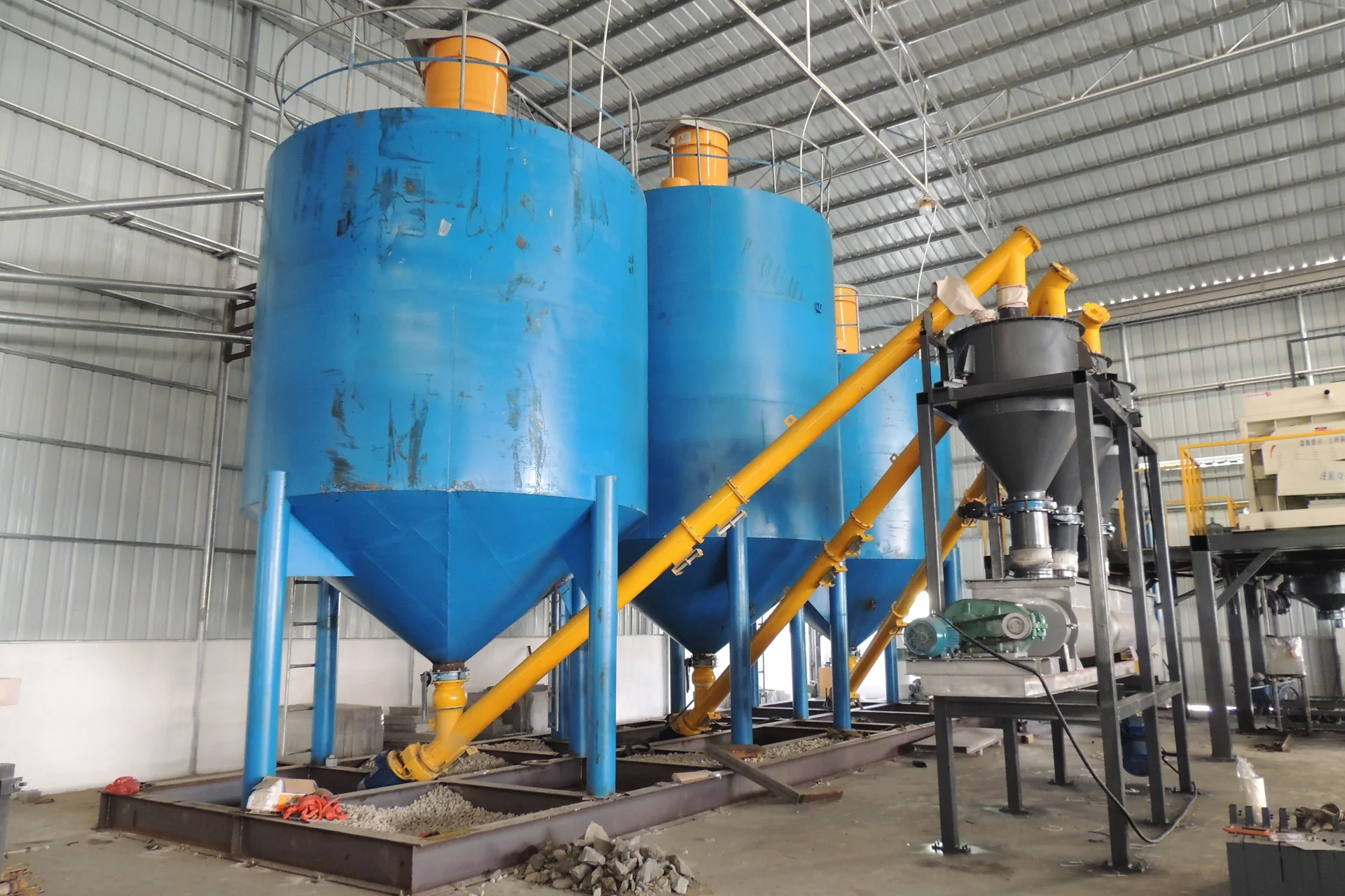
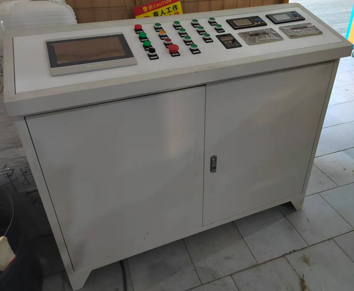
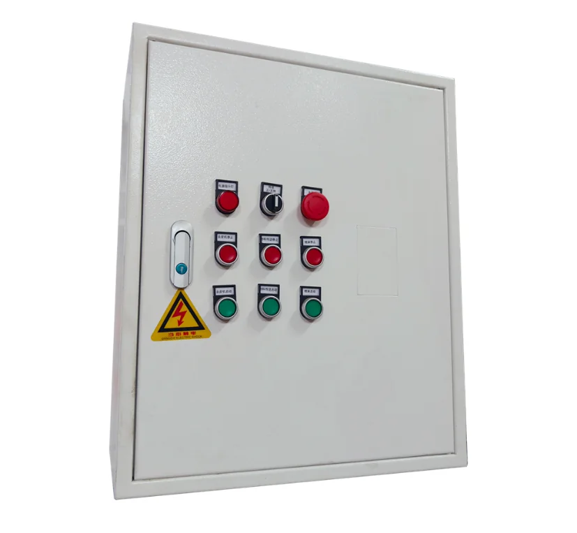
| 1 | Preparation & metering | HDSL-001 | 8640 × 350 × 1100 | 2 | 11 kW | 22 kW | |
| 2 | Preparation & metering | HDPDA-001 | 9000 × 800 × 800 | 1 | 2.2 kW | 2.2 kW | |
| 3 | Preparation & metering | HDFL-001 | 1.2 m × 1.5 m × 1.4 m | 1 | 0.55 kW | 0.55 kW | |
| 4 | Slurry metering system | Preparation & metering | HDAS-001 | 1.2 m × 1.5 m × 1.4 m | 1 | 0.55 kW | 0.55 kW |
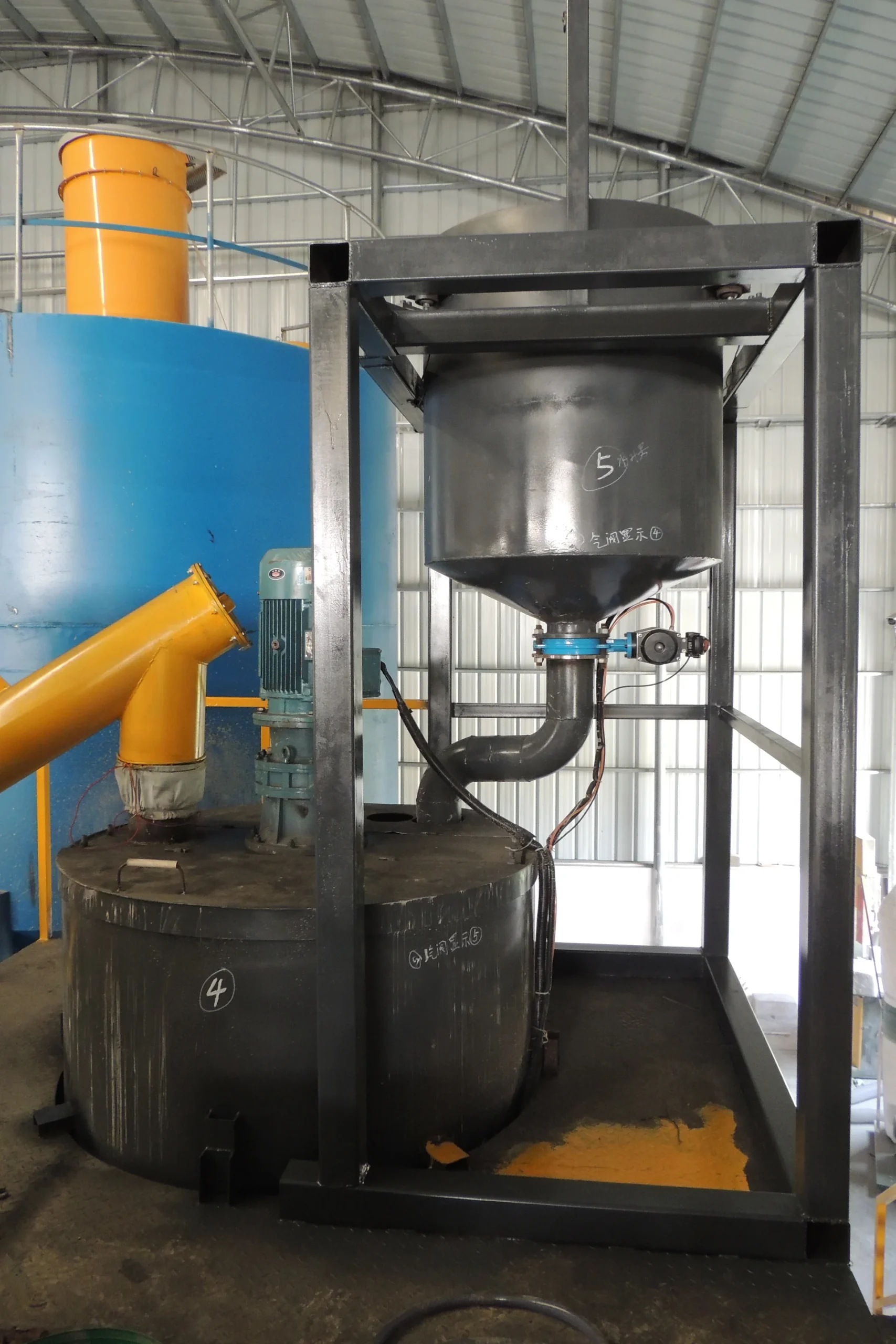
| 5 | Preparation & metering | HDFL-001 | Ø1310 × H1950 | 1 | 0.55 kW | 0.55 kW | |
| 6 | Preparation & metering | HDSL-001 | Ø1100 × H1140 | 1 | 0.55 kW | 0.55 kW | |
| Physical foaming & mixing | |||||||
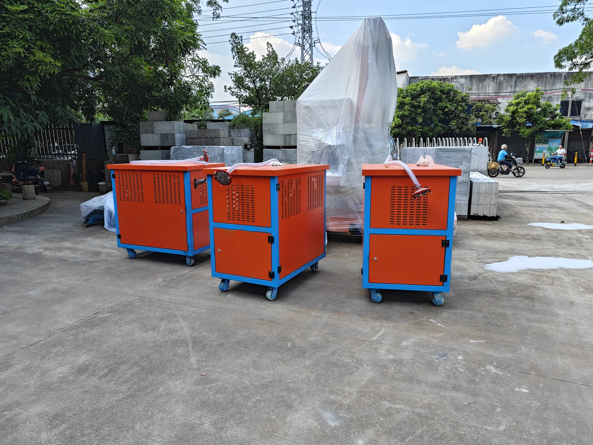
| 7 | Physical foaming & mixing | HDKWF1-001 | 1150 × 750 × 1140 | 1 | 7.5 kW | 7.5 kW | |
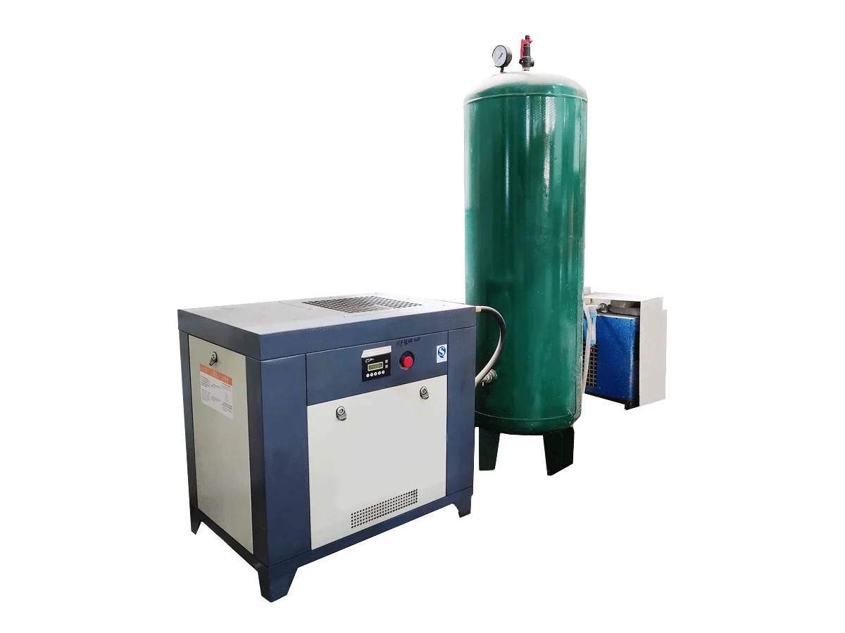
| 8 | Physical foaming & mixing | HDKY-001 | L1500 × W500 × H2000 mm, air receiver0.8 m³*1 | 1 | 15 kW | 15 kW | |
| Preparation & metering | |||||||
| 9 | Preparation & metering | — | 5000 × 3500 × 1500 | 1 | — | — | |
| Physical foaming & mixing | |||||||
| 10 | Physical foaming & mixing | EPSJB-04 | 3900 × 2000 × 2100 internal chamber: 2580 × 1588 × 1700 | 1 | 22 kW | 22 kW | |
| Preparation & metering | |||||||
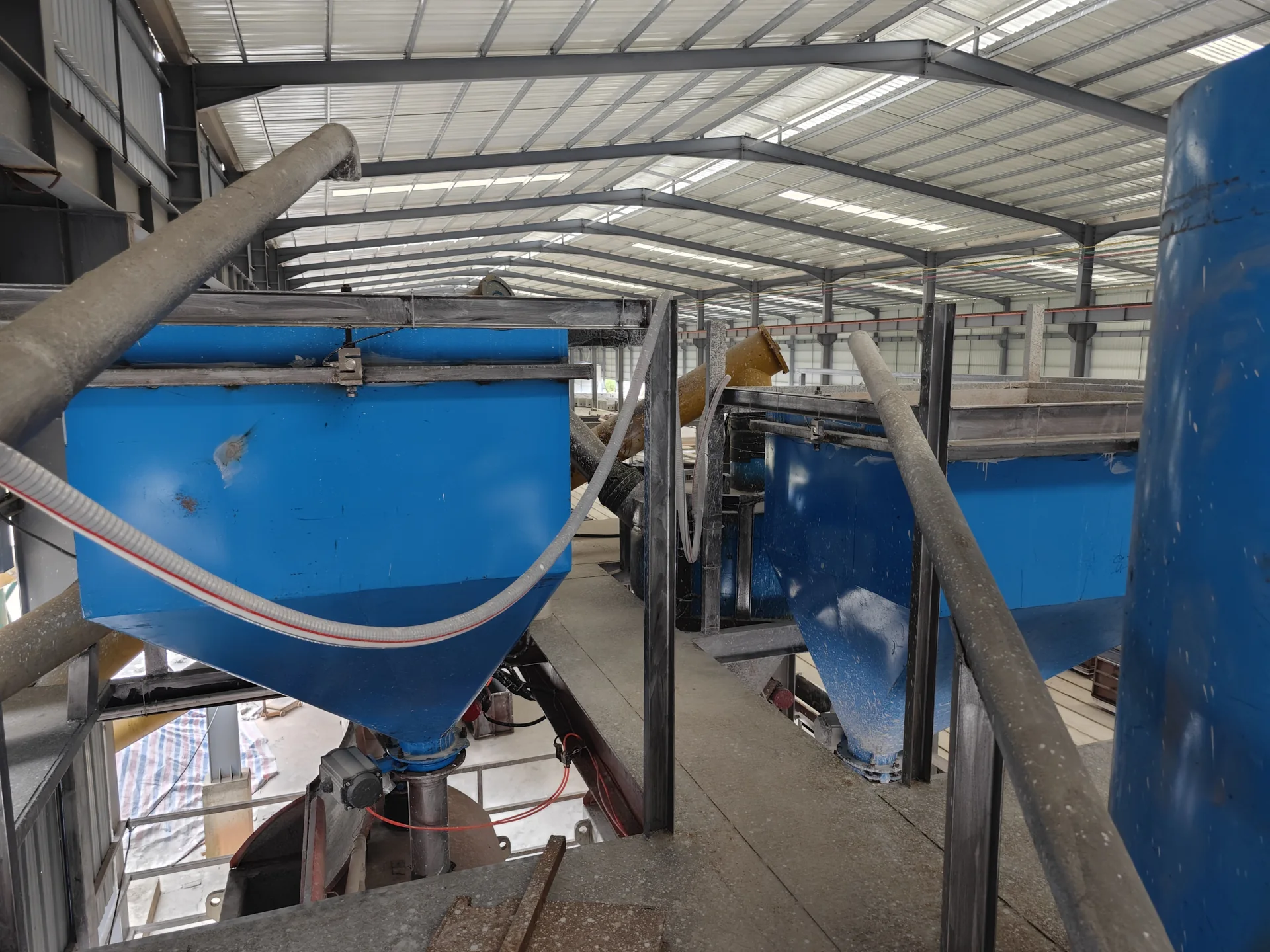
| 11 | Slurry storage tank | Preparation & metering | — | — | 2 | 22 kW | 44 kW |
| 12 | Waste-slurry storage tank | Preparation & metering | — | — | 2 | 11 kW | 22 kW |
| 13 | Submersible slurry pump | Preparation & metering | 100YZ | — | 1 | 22 kW | 22 kW |
| Cutting & finishing | |||||||
| 14 | Cutting & finishing | HDSQ1-003 | 9000 × 3300 × 3650 (high-precision rotary configuration) | 3 | 46.8 kW | 140.4 kW | |
| 15 | Cutting & finishing | HDOSD1-001 | 3000*1000*2100 (including powered line) | 3 | 22 kW | 66 kW | |
| Handling & stacking | |||||||
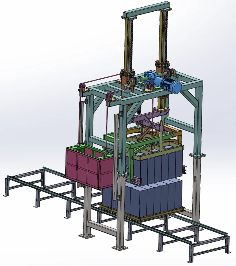
| 16 | Handling & stacking | HDKDR-001 | 4.9 m × 2.8 m × 4.2 m | 1 | 5 kW | 5 kW | |
| 17 | Handling & stacking | HDTH-006 | 4800 × 2600 × 3800 | 3 | 6.2 kW | 18.6 kW | |
| 18 | Handling & stacking | HDTH-005 | 2430 × 1330 × 3900 | 3 | 7.5 kW | 22.5 kW | |
| Moulding, curing & circulation | |||||||
| 19 | Moulding, curing & circulation | HDBD2-001 | 1800 × 1080 × 400 | 10 | 1.2 kW | 12 kW | |
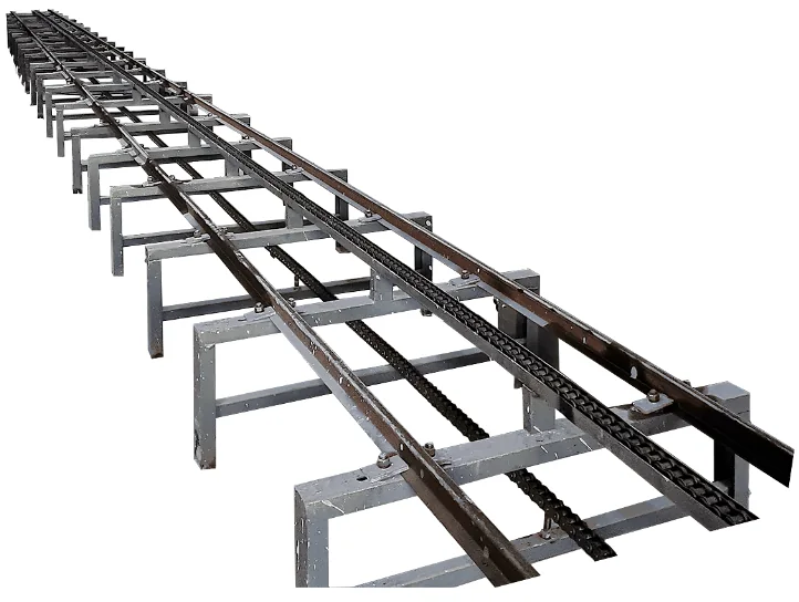
| 20 | Moulding, curing & circulation | TM-001 | 12 m × 1.1 m | 1 | 2.2 kW | 2.2 kW | |
| 21 | Moulding, curing & circulation | HM-001 | 12 m × 1.1 m | 1 | 2.2 kW | 2.2 kW | |
| 22 | Moulding, curing & circulation | JZ-001 | 12 m × 1.1 m | 1 | 2.2 kW | 2.2 kW | |
| 23 | Moulding, curing & circulation | HDZD-001 | 4 m × 1.1 m | 9 | 0.3 kW | 2.7 kW | |
| 24 | Moulding, curing & circulation | HDZD-002 | 4 m × 1.1 m | 9 | 0.3 kW | 2.7 kW | |
| PLC, electrical & tooling | |||||||
| 25 | PLC, electrical & tooling | HDKZ1-001 | 1300 × 1100 × 400 | 1 | — | — | |
| 26 | PLC, electrical & tooling | HDCBD1-001 | 700 × 500 × 400 | 1 | — | — | |
| 27 | PLC, electrical & tooling | — | — | 1 | — | — | |
| PLC, electrical & tooling | |||||||
| 28 | Production equipment | HDCM1-001 | 1420 × 1220 × 630 | 1162 | — | — | |
| 29 | Production equipment | HDCM1-002 | 1436 × 1336 × 180 | 1600 | — | — | |
| Moulding, curing & circulation | |||||||
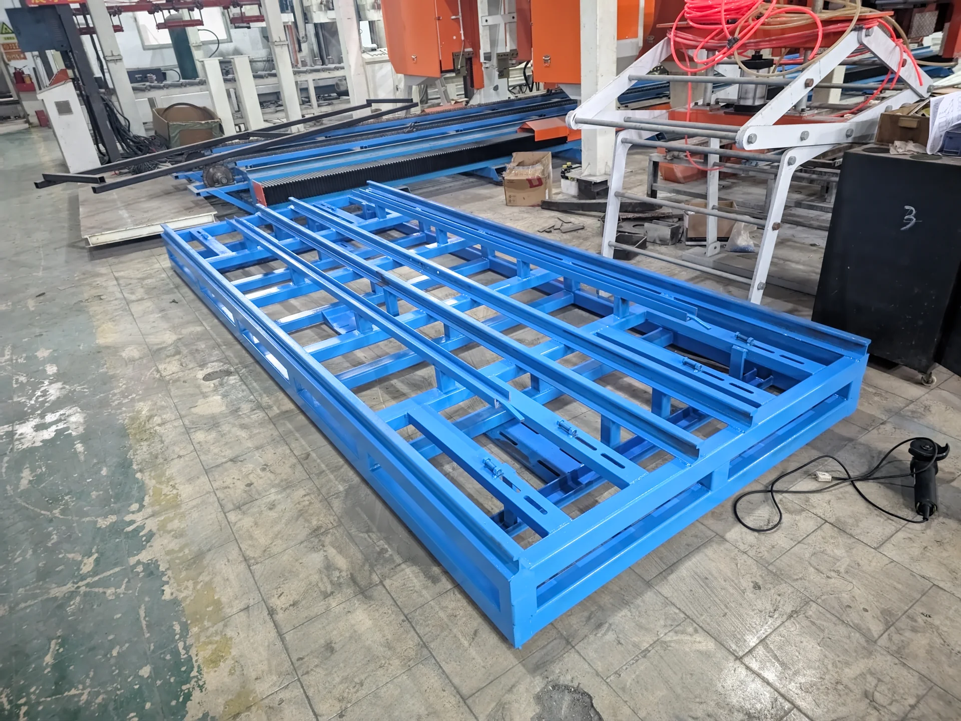
| 30 | Winch-driven conveyor line | Moulding, curing & circulation | HDCM1-0013 | 1000 × 1000 × 550 | 10 | 7.5 kW | 75 kW |
| PLC, electrical & tooling | |||||||
| 31 | Steel wire rope | Production equipment | — | — | 1 | — | — |
PROJECT DELIVERY / TURNKEY SUPPORT
A factory proposal connects the project country, raw materials, target product and capacity, product dimensions, factory land, utilities, budget and automation requirement. The service and supply responsibilities are agreed for each project.
Evaluate representative samples from the project location before selecting the final process.
Adjust the formulation and material ratios against the test results and target product.
Confirm product dimensions and the product-specific preparation, forming, curing and finishing process.
Coordinate land, buildings, storage, material flow, foundations and utilities.
Match capacity, automation, budget, moulds and process interfaces to the agreed factory scope.
Prepare the agreed machines, tooling and controls against the approved configuration.
Check applicable equipment and delivery scope before shipment.
Coordinate packing, loading and destination requirements with the project shipping plan.
Install and connect the agreed equipment after site conditions are ready.
Check machine sequences and trial production with the selected materials.
Train operators in safe use, production sequence and routine maintenance.
Plan maintenance communication and spare-parts support for the installed equipment.
REAL HENGDE PROJECTS
HENGDE projects selected by product family, process route, capacity and current delivery stage.
Tirana, Albania 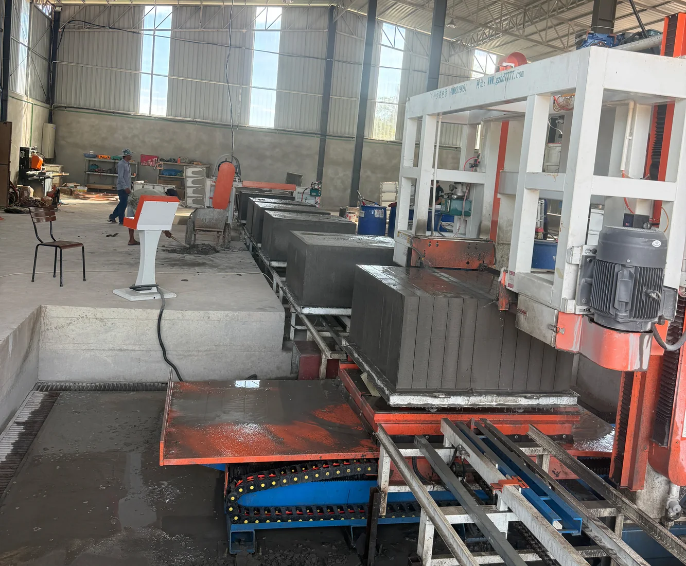 Phnom Penh, Cambodia
 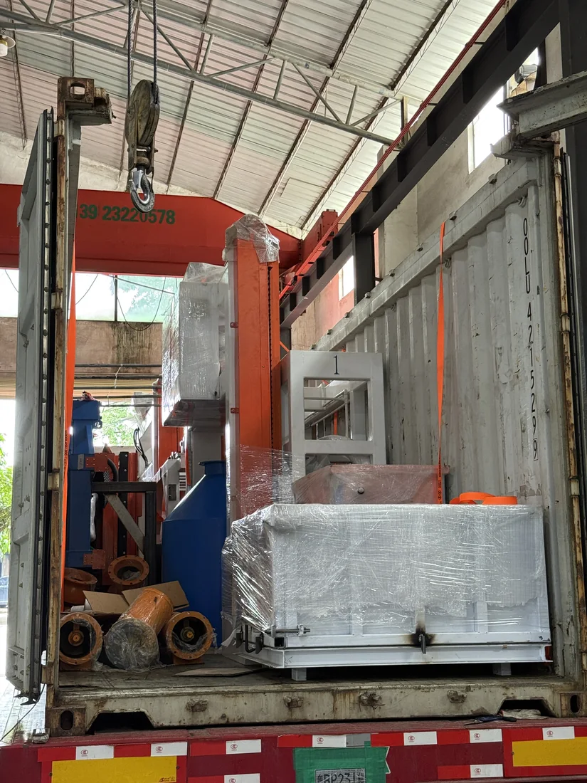 Indonesia
 Review local binders, mineral inputs, process water and the physical-foaming system against this capacity-specific CLC configuration.
Review the available binder, mineral input, process water and physical-foaming input against the target CLC block.
Recycled mineral inputs require source-specific sorting, sampling and trial production before they enter the line design.
Test results guide slurry proportions, water ratio, preformed-foam dosage, mixing sequence and mould filling.
The confirmed curing, demoulding and cutting condition then determines mould circulation and downstream handling.
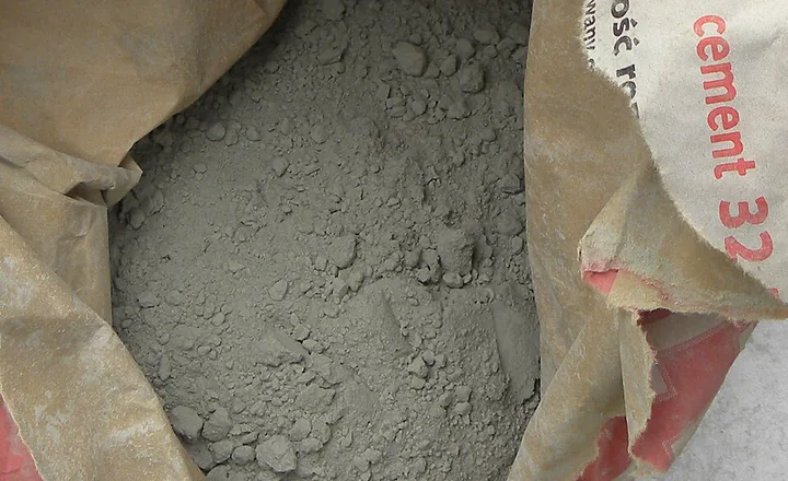
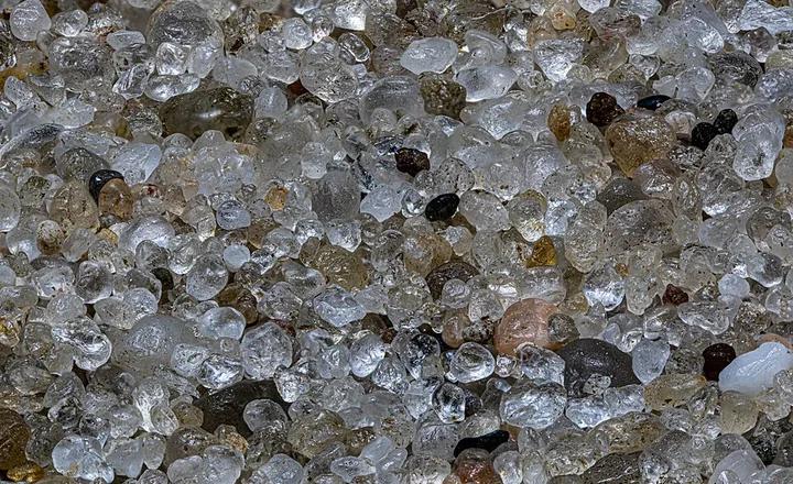
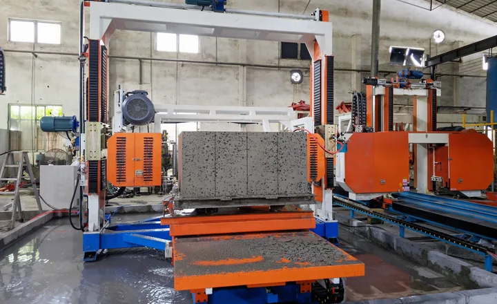
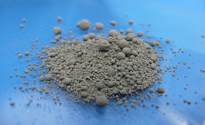
Sampling and project-specific review required.
Sampling and project-specific review required.
Sampling and project-specific review required.
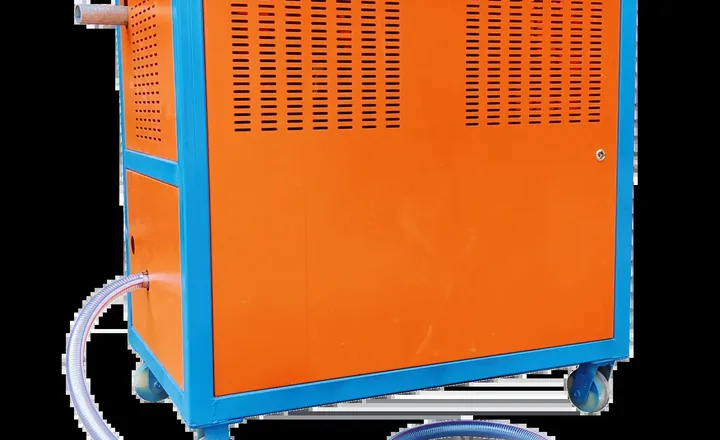
Sampling and project-specific review required.
A planned collection and settling loop can reduce uncontrolled slurry discharge and recover process water. The exact civil works, pump selection and reuse rate depend on the project layout and tested material system.
Raw-material availability varies by country. Send HENGDE your local material information before the final production-line configuration is confirmed.
Representative material photographs: cement, Szlomo Lejb / Sumek101; river sand, Krzem Anonim; fly ash, Ablazejo. Licensed under applicable CC BY-SA / GFDL terms. HENGDE project and testing photographs are identified separately.
PROJECT PLANNING
Tell us your target product, project location and planned output. The selected 1000 m³/day configuration is included automatically.