How to Read a 100 m³/day CLC Block Production Line Equipment List
A 100 m³/day CLC equipment list should be read as a connected production system, not as 24 unrelated purchasing lines. Each machine supports a stage in the material and mould flow. If one stage is omitted or undersized, the stated daily output may not be achievable in practical operation. The HENGDE 100 m³/day CLC block production line currently presents a standard-reference set of 24 identified equipment items. That display helps buyers understand media coverage and equipment roles. It does not mean that every model, quantity or power value is universal for every project. The featured image is an AI-generated editorial configuration illustration. It is not…
A 100 m³/day CLC equipment list should be read as a connected production system, not as 24 unrelated purchasing lines. Each machine supports a stage in the material and mould flow. If one stage is omitted or undersized, the stated daily output may not be achievable in practical operation.
The HENGDE 100 m³/day CLC block production line currently presents a standard-reference set of 24 identified equipment items. That display helps buyers understand media coverage and equipment roles. It does not mean that every model, quantity or power value is universal for every project.
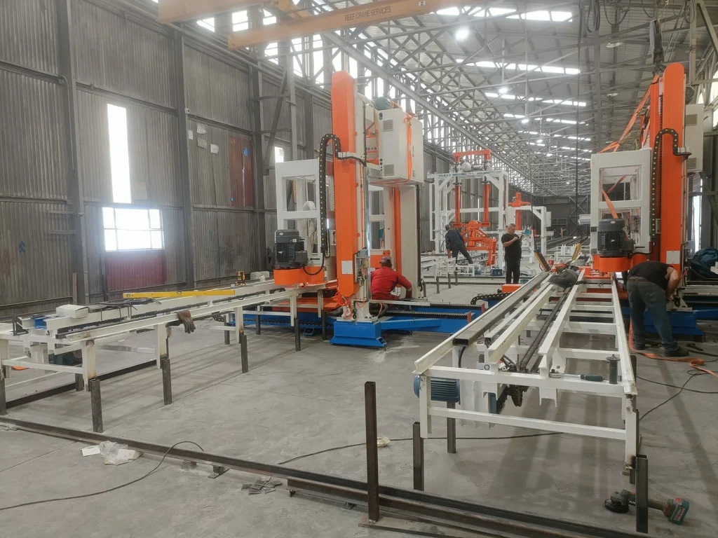
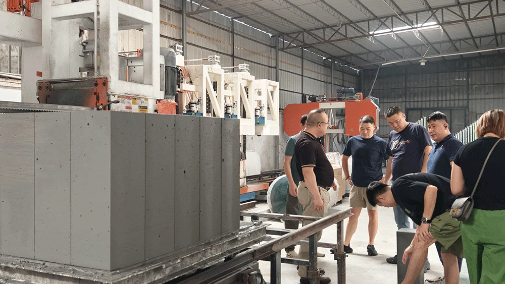
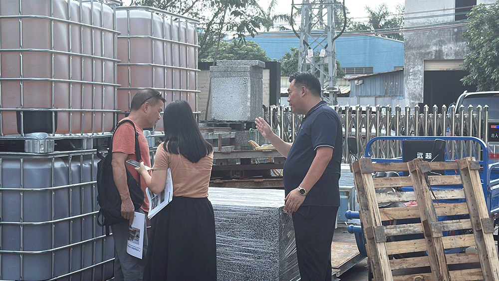
The featured image is an AI-generated editorial configuration illustration. It is not a final BOM, customer-site photograph or engineering drawing. The article also shows real HENGDE equipment photographs.
Start with the process groups, not the row numbers
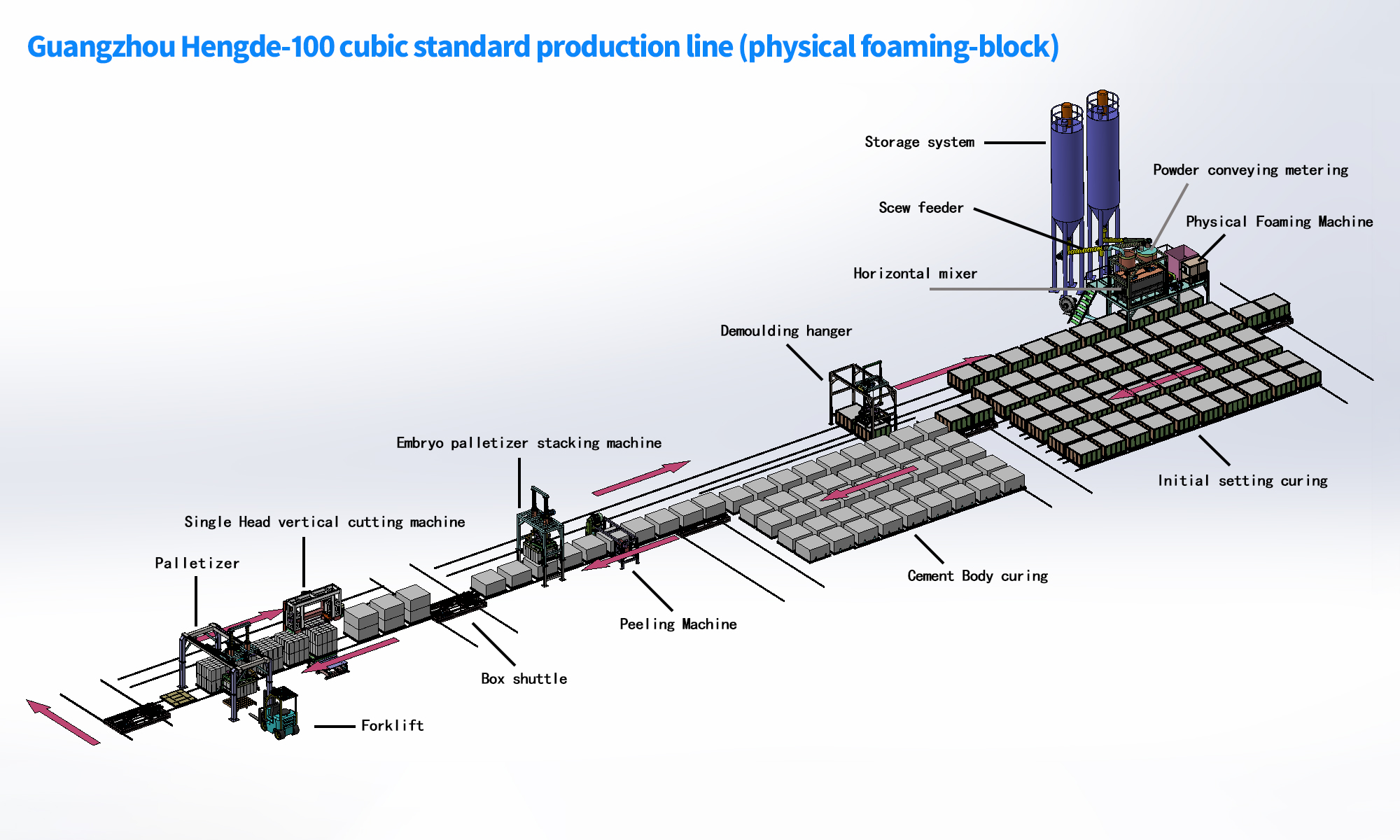
A useful equipment list follows the production sequence. The 24-item reference can be understood in seven functional groups:
- raw-material feeding and conveying;
- powder and water metering;
- physical foam preparation and mixing;
- pouring, moulds and mould circulation;
- demoulding and cutting;
- transfer, feeding, discharging and stacking;
- PLC, electrical cabinets and remote support modules.
This grouping makes it easier to check whether the quotation covers the complete route from raw material to finished block.
Feeding and metering establish batch repeatability
The front end normally includes a screw feeder, belt conveyor, powder metering system, conveyor-linked metering hopper and water metering system. Their task is not simply to move material. They must deliver the planned batch quantities in a stable sequence.
Read the list for hopper volume, feeding method, weighing arrangement, access for cleaning and the way moisture corrections will be handled. A listed conveyor without its supporting metering or control scope may not represent a complete batching function.
Relevant equipment pages include the screw feeder, belt conveyor, powder metering system and water metering system.
Foaming, air supply and mixing form one operating unit
The physical foaming machine, air compressor, operating platform and special mixer must be evaluated together. Foam quality depends on controlled water, air and foaming-agent preparation. The mixer then has to distribute that foam through the cementitious slurry without destroying the required pore structure.
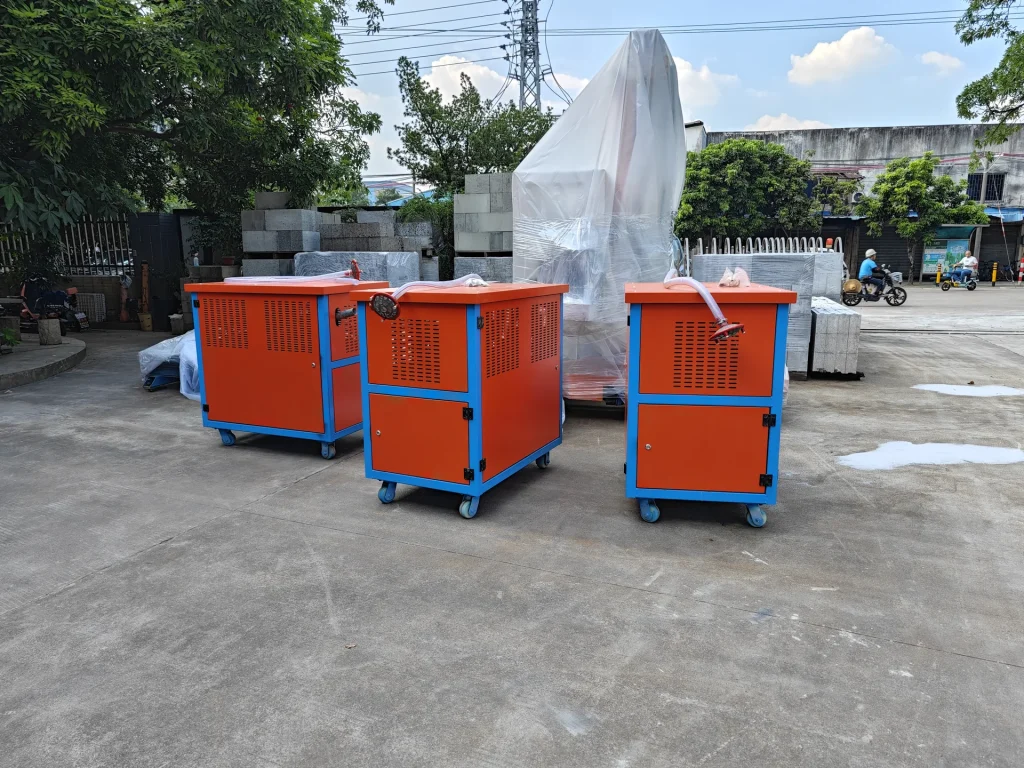
Check whether the compressor and foam-delivery connections are included, how the foaming unit communicates with the batch sequence and whether the mixer is sized for the intended batch rhythm. The model label alone cannot answer those questions.
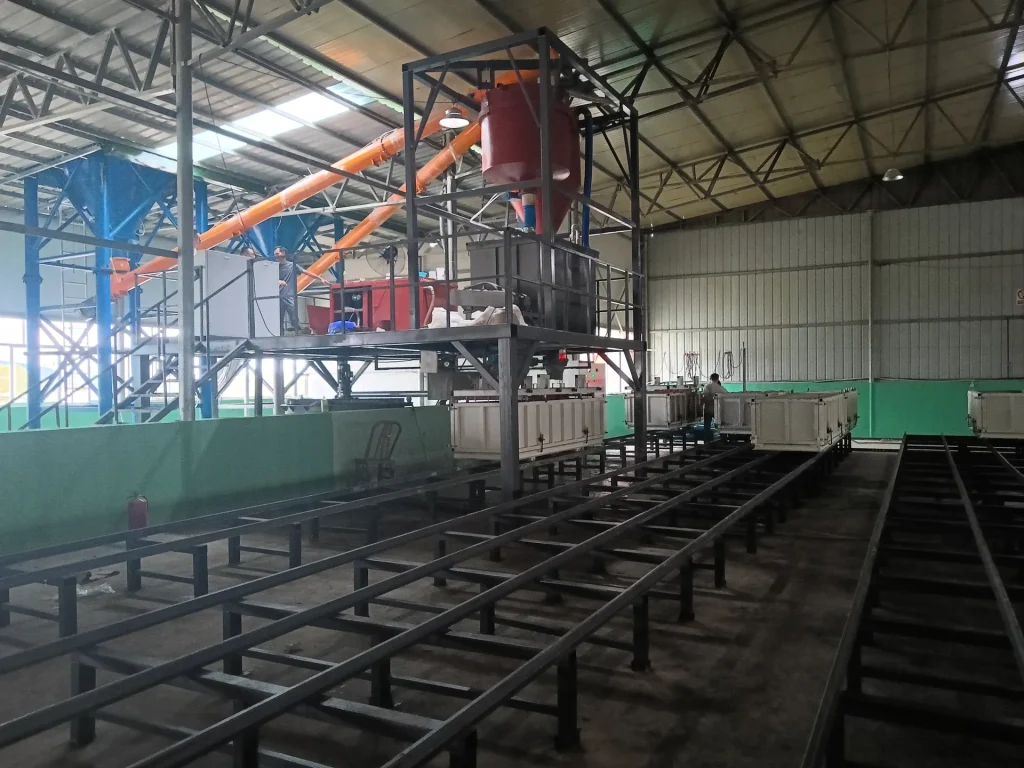
The operating platform also affects maintenance access, safe sampling and cleaning. It should be evaluated as part of the equipment arrangement rather than treated as decorative steelwork.
Mould and circulation equipment determine factory rhythm
Pouring line, moulds, demoulding line and return-mould line connect the wet process to curing and cutting. Mould quantity must reflect batch output and curing time. Rails, ferry cars and circulation equipment must support the required movement without blocking operator or forklift routes.
The 100 m³ reference list includes the mould as an identified item, but its dimensions and quantity must follow the block format and production plan. A commercial quotation should also state which mould accessories, release preparation and maintenance items are included.
Cutting and peeling must match the green-body condition
The single-head vertical cutting machine and peeling machine prepare the cured body for accurate finished blocks. Their performance depends on the material reaching the correct cutting condition. A machine cannot compensate for unstable mixing, uneven curing or poor mould preparation.
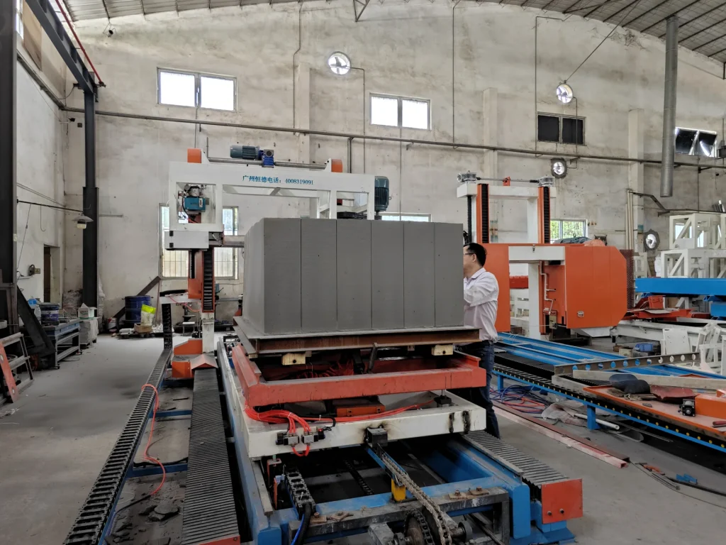
Compare cutting direction, product dimensions, handling method, blade or wire arrangement, safety guarding and the transfer into and out of the machine. The cutting-system overview explains why a cutting upgrade must be connected to the full line rhythm.
Handling equipment is production equipment, not an optional afterthought
Demoulding hanger, automatic palletizing machine, green-body stacking machine, ferry car, automatic feeding line and automatic discharging line manage the movements around curing and cutting. These items influence labour, product damage, buffer capacity and floor space.
Buyers should ask which movements remain manual, which need lifting equipment and which are controlled automatically. The answer affects both initial cost and daily staffing. It also changes the required foundations, rails and safety zones.
PLC and electrical scope need a clear interface list
The platform PLC main control cabinet, foaming electrical cabinet and remote module support sequencing, interlocks, alarms and authorised parameter changes. A list should identify the controlled machines, supplied sensors, cabinet boundaries and communication method.
Do not assume that every motor, field cable, installation cable or local distribution cabinet is included because “PLC” appears in one row. Confirm the responsibility boundary between the machine supplier, the line-control scope and the customer’s factory electrical system.
How to read model, quantity and power columns
A well-structured table may include model or specification, quantity, unit power, total power and configuration notes. These fields should be used carefully:
- Model or specification identifies the proposed equipment version, dimensions or duty.
- Quantity should reflect the production rhythm and any required parallel operation.
- Unit power is the connected rating of one unit, not the whole factory’s running load.
- Total power should follow quantity and should not be confused with simultaneous operating demand.
- Configuration should clarify included accessories, control level and project boundary.
If a value is blank while the source is being reconciled, blank does not mean zero and it does not mean the machine is unnecessary. Ask for the project quotation version and its issue date.
Compare the list with the layout and product requirement
An equipment list becomes useful when it agrees with the layout. Every feeder needs a receiving point; every mould needs a circulation path; every cutting machine needs incoming and outgoing handling; every cabinet needs controlled equipment and safe cable routes.
Before approving a 100 m³/day CLC equipment list, confirm the target block dimensions, raw materials, density and strength requirements, curing conditions, working shifts, factory space and desired automation level. HENGDE then converts the reference configuration into a project-specific BOM and arrangement.
Use the linked equipment rows on the 100 m³/day line page to open individual machine details. When ready, send the project country, materials and output target for an engineering review.
Final capacity, process and equipment configuration require project-specific engineering verification.
REAL HENGDE REFERENCE
Equipment, project or engineering evidence
Discuss your production line project with HENGDE.
Share your product, project location, target output and available materials with the HENGDE team.
Discuss Your Project